- Home
- Lean Principles
- Machine Selection
- Mold Design
- Mold Interlocking
- Mold Making
- Plastic Material Technology
- Molding Process
- Plastic News
- What's New
- Privacy Policy
- Disclaimer
- Site Map
- Poll
- Polishing
- 3D Rapid Prototyping
- Molding Companies
- Contact Us
- Proven Thinwall Packaging Mold Designs For Sale
- MOLD WEIGHT CALCULATOR
- Material Selection Service
- HOT RUNNER VERSUS COLD RUNNER
3 Plate Mold Design For Plastic Injection Molding
3 plate mold designs are used in multi cavity cold runner mold
tooling when a 2 plate mold design does not permit a suitable gate location.
SCROLL DOWN TO SEE DESIGN PRICES
Pay by PayPal or Credit Card
3 Plate Mold Example.
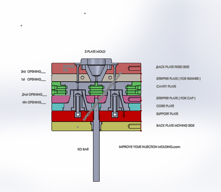
 Figure 1: two cavity 3 plate mold for 47mm alcohol cap
Figure 1 shows an assembly section of a three plate mold producing a 47mm cap. This design allows the gate to be placed on the top of each cap. The caps and cold runner are ejected by their own individual stripper plates during mold opening.
You will need Adobe Reader (the latest version is recommended) installed on your computer in order to open and read this file. You can download Adobe Reader here (a new window will open so you can download it without leaving this page).
If you want to open the file in your browser window, just click on the link (not all browsers have this feature). However, if you want to download the file to view later, then right-click on the link and choose "Save Target As" or "Save File As." Then select where you want to save the file on your hard drive.
Once you have saved the file, locate where you saved it, and double click to open it.
In order to print, open the downloaded file, and select the "Print" option from the e-book
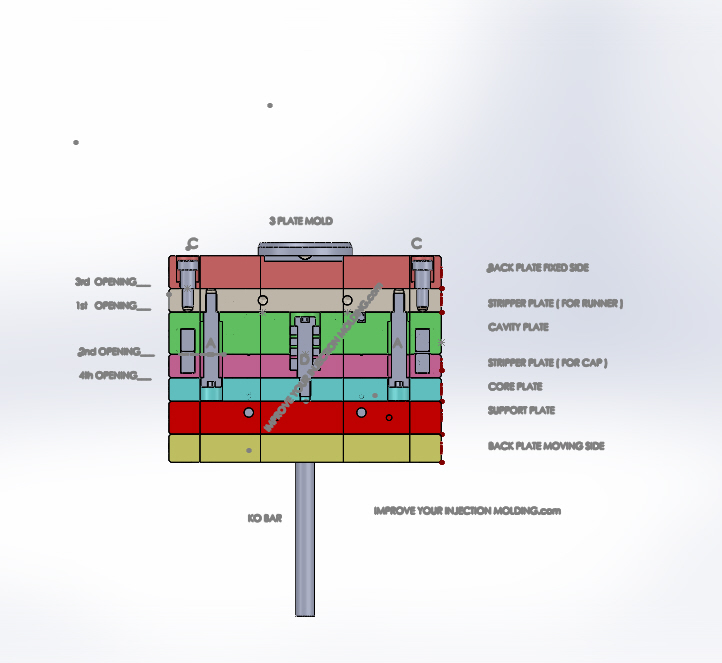
 Figure 2: limit screws (A) required for 1st opening limit
During the opening sequence the first split is between the cavity plate and the stripper plate (for runner) due to spring pressure (see spring in figure 3) for the distance defined by limit screws (A) in figure 2. At this stage the runner is exposed but held firmly to the mold by the sucker pins (the sucker pins are labelled in Figure 1) .
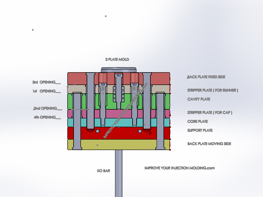
Right click here to download Figure 2 in PDF format. Figure 3: limit screws (B) required for 2nd opening limit
As the mold continues to open, the 2nd split is between the cavity plate and the stripper plate (for cap) for a distance defined by limit screws B in figure 3.
Right click here to download Figure 3 in PDF format. Figure 4: limit screw C
The 3rd stage opening is between the back plate on the fixed side and the stripper plate (for runner) for a distance defined by limit screw (C) in Figure 4 which ejects the runner off the sucker pins. The runner falls to the ground.
At this stage the mould is fully opened, so the KO bar must be initiated by the machine ejector to remove the caps from the mold tool which is the 4th.
Should I Use a 3 Plate or 2 Plate Design For My Part?
When designing a cold runner mold tool a 2 plate mold design should be considered first because it is easier and cheaper to make.
One potential limitation of a 2 plate design is that the gate must come from the side of the part which has the potential to cause the following quality issues in some parts: weld lines, jetting, unfavourable shrinkage rates and wall thickness variation due to core shift in tall parts. Longer flow paths may also be required which can place higher demands on the injection molding machine and consume a lot more energy.
Having said that, the 2 plate mold is suitable for many types of plastic parts.
The advantage of a three plate mold design is that it permits the gates to be located on top or bottom of the part at any point on the surface. Well placed gates will produce quality parts every cycle.
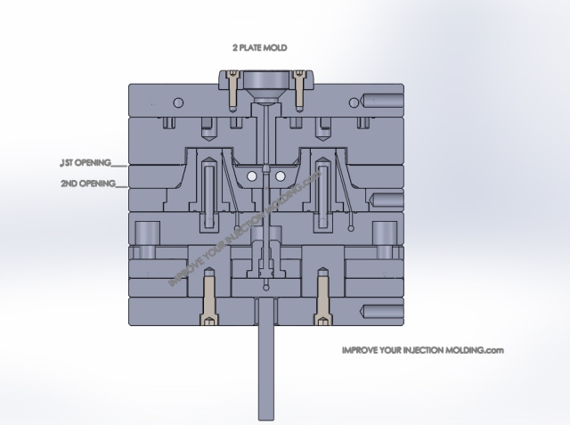
Figures 5 & 6 are an example of a 2 plate & a 3 plate mold design respectively for the same 47mm alcohol cap. Notice the different gate locations.
 Figure 5: two cavity 2 plate mold for 47mm alcohol cap
 Figure 6: two cavity 3 plate mold for 47mm alcohol cap(same as figure 1)
Mold Designs For Sale
Buy Now:
Pay by PayPal or Credit Card
Click here to purchase BOTH designs for just US$19.95
Both Mold Designs Include:
- full 3D assembly drawing
- 3D drawing of each mold component
- full cooling system design for quick cycle time
- tapered interlocks for robust alignment between fixed & moving side to maintain even wall thickness
- Material selection guide pdf for mold plates & inserts
- both primary & secondary venting requirements to ensure part quality
- gate detail
- fitting clearance requirements for core & cavity inserts in the plates to aid in longer mold life
- design for manufacture principles which ensures molds are easy to make
- design for easy maintenance, for example, limit screws can be removed in the moulding machine for greater access for mold cleaning
Buy today & start manufacturing tomorrow!
Why would you want to buy?
With these 3D designs drawings you can:
- use them as a reference for your own tool design development (for toolmakers, design engineers and injection molders)
- add your own cap design for reduced mold design time
- modify the mold size or any other component drawing to suit your own needs (technical support is available free of charge)
If you have a question before purchasing then click here contact us.
So what are you waiting for?
Buy now:
Click here to purchase BOTH designs for just US$19.95
Return from 3 Plate Mold to Injection Mold Design
Return from 3 Plate Mold to Improve Your Injection Molding Home Page


