- Home
- Lean Principles
- Machine Selection
- Mold Design
- Mold Interlocking
- Mold Making
- Plastic Material Technology
- Molding Process
- Plastic News
- What's New
- Privacy Policy
- Disclaimer
- Site Map
- Poll
- Polishing
- 3D Rapid Prototyping
- Molding Companies
- Contact Us
- Proven Thinwall Packaging Mold Designs For Sale
- MOLD WEIGHT CALCULATOR
- HOT RUNNER VERSUS COLD RUNNER
Plastic Parts Design and Material Selection– How To Do It Right The First Time
The most important first step in plastic parts design and material selection is to list the environmental conditions that the part will be exposed to.
For example, will it be subject to elevated temperatures? If so, for how long and how often? Plastic behaves differently at different temperatures.
This is just 2 questions of several that need to be answered before one is in a position to select the most suitable plastic material.
Plastic part failure in the field is often a result of poor research.
Delivery lead times are becoming so short that often plastic parts design and the material selection process are not given the attention and time needed to make proper decisions.
This is where the process of Concurrent Engineering can be of great benefit to a new product project. Concurrent Engineering brings together the mold maker, molder, part designer, plastic supplier, marketer and end user so that the proposed plastic parts design can be analysed for economic and technical viability. That is, whether or not it can be made at a particular cost so that all parties involved can make a profit.
Part Shape
The next step is to decide on the shape of the part and the wall thickness. This can be done by people who have the specialized knowledge such as molders, mould makers and industrial designers.
The use of Finite Element Analysis (FEA) can also be of great benefit. FEA will identify any potential weak areas in the part design. Keep in mind however, the computer generated results are only as accurate as the information that is fed into it. So get accurate information.
Mold Design
When you are confident that the part will work in the field, an injection mold maker must check that the part can actually be made. A mould needs to be designed around the part. Where is the gate to be located? Is more than one gate required? Where are the parting line surfaces? How will the part be ejected? For complicated part shapes, computer simulation techniques must be used.
Once these mold design points are answered, make sure the plastic material selected is capable of filling the mould cavity. Some materials such as polycarbonate are very viscous so a thick wall section is required to be able to make full parts.
In addition to this, in order to have long term reliable production, there are a number of other things to consider. After all, we do want a project to work don’t we?
Draft
Draft can be the enemy for part designers. Too much draft on a cosmetic part can detract from its appearance. But the fact is, draft is required to make quality parts at fast cycle times.
Draft angle should be at least 0.5 degree per side but 3 degrees is better. The greater the draft the fewer scratches and marks will be present on the parts.
What’s more, draft is required for stacking purposes. Parts with large draft angles can be easily stacked and separated. They also reduce the combined stack height of the parts so that transportation costs are kept as low as possible.
Uniform Wall Thickness
The easiest parts to mould have uniform wall thickness. If, for some reason, the part has to be thicker in a particular section, then consider locating the gate in this section so that sink marks can be avoided.
There are some other circumstances when uniform wall thickness does not apply. Ribs are often made thinner than the nominal wall thickness to reduce the sink mark which detracts from its appearance.
Radii
Any sharp corners on the part will not only make it more difficult to eject from the mould, it will also create stress concentrations and likely lead to part failure.
There should be at least 0.5mm radii everywhere. Bigger radii will make the part stronger and increase its lifespan. Bigger radii will also help with processing by improving material flow around corners.
Dimple

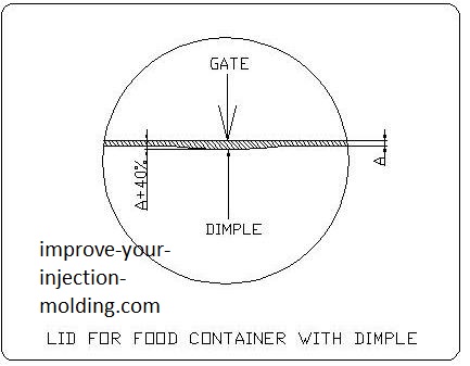
Gate brittleness ( which can cause part failure) is the result of stress set up in the gate area. In practise, these stresses are usually caused by the application of incorrect moulding conditions, such as too high or too long hold pressure. Risk of gate brittleness is substantially reduced by having a dimple opposite the gate by locally increasing the wall section by 40%.
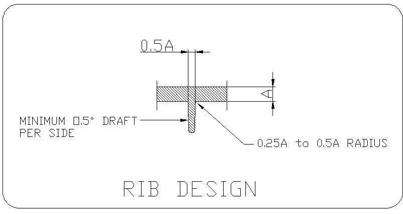
Standard Rib Design

The main function of ribs is to improve the rigidity and strength of a molded part. They may also be used to help flow during processing and decrease part warpage.
Ribs must be carefully designed in order to minimize sink marks and stress concentrations.
Minimizing sink marks is especially important for parts that have a perfectly clean matt or glossy finish such as housings for electrical appliances. The width of the rib can be as low as 50% of the adjacent wall in order to reduce the effect of sink.
Keep in mind however, that with such a thin rib, the part will be harder to process so good mould design and molding machine capabilities are critical. The machine must be capable of applying adequate hold pressure in the rib area during processing.
Ribs have the potential to create venting issues so mold design must take this into consideration.
Alternate Rib Design

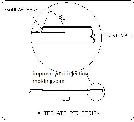
The standard rib design is very effective in creating strength in a particular area of a part. However, this type of rib can cause quality issues when venting is not taken into consideration. It can also create a high nest height which means fewer parts will fit on a standard transportation pallet which increases freight costs.
An alternative rib design is often used in the food packaging industry. To minimize warping, an angular panel is designed into a lid which acts just like a standard rib but will not cause quality issues. The lids will also maintain a low nest height.
A lid also has another built in rib which is the skirt wall. The skirt wall will also aid in minimizing warp.
Conclusion
The most critical aspects of plastic parts design is to know where it will be used and what conditions it will be exposed to. Without this knowledge there is no chance of a successful moulding project.
At the start of a new part project, here is a list of questions to answer before selecting the plastic material:
1. What temperature range will the part be exposed to and for how long?
2. What are the mechanical loads?
3. What are the nature of loads – cyclic or constant?
4. Direction of loads – does the load act in one or more axis?
5. Environmental factors such as sunlight, water or chemicals exposure?
6. Electrical requirements?
7. Tolerance requirements? Does the part fit with other parts?
8. What are the long term effects on the chosen material? Is there any information available?
Return from Plastic Parts Design to Plastic Injection Mold Design For Interlocking


